Days are staying cooler now as we approach winter, but work still progresses on the house. This week, we see changes to both the exterior and interior as the painters came in to prime all the exposed trim boards so the winter doesn't damage anything. Inside, HVAC continued to install the main supply and return trunks and the plumbers are installing supplies and drains all over the house.

We lucked out and visited the house on a cold but sunny day after an exporatory shopping trip to a plumbing supplier and a leaded glass creator. We still need to nail down specifics on the plumbing fixtures, and it's proving to be more difficult than expected because there's so much selection out there. Every time we visit a supplier, it seems like we find something new that we like. We went to a local leaded glass craftsman to look into getting a piece made for the new transom above the sliding door in the kitchen. There were some patterns that we like, so we'll probably be revisiting him to get it created.
Here's what the house looks like now. You can see the grayish primer is on the trim and there was some work done to the turret windows. The carpenters haven't returned yet to finish up the rest of the trim but that can wait until we have a battle plan in place with the bank.
All the existing trim was shot with a primer after caulking the seams. The primer will help protect the wood over the winter time, until we can get the finishing paint up there. They taped off the copper, but didn't care about overspray on the ICF, which is fine since it will all be covered with shingle. Having the primer up there makes a big difference in the appearance of the trim. Since the seams were caulked, then painted, all the seams in the overhang and window trims disappear and everything looks much more uniform. There's more trim to be installed, but it might take a back seat to getting the exterior up, which is fine since it's more of a finishing thing.

You can see some overspray on the ICF, but some of the trim was hand painted with a brush. They sprayed the cladding above the garage door even though this will be behind the shingle. It doesn't hurt to have this wood protected and adds another layer of rot protection behind the shingle. We landed on a design for the brackets that will flank each door, but it has yet to be installed. The top of the arch is actually Azek, but when it's painted, you can't really distinguish it from rough-sawn ceder.

Here, you can see a seam in the overhang that was caulked and painted. The seams aren't really visible and I'm sure once you get the white paint up there, it will all but disappear. The overhang vents were indiscriminately shot with primer too since they'll just end up being painted white anyways. Some of the tape they used to mask the copper drip edges is still on the house, but I have no doubt they'll remove it eventually. The overspray is only about an inch and it's very even; a mark of an experienced painter. There's no other way to hit the bottom of the trim without spraying the house. In future repaints when the shingle and trims need to be repainted, they'll probably shoot the trim first, then mask it to shoot the shingle.

Lots of plumbing work this week as the plumbers have almost completed the pass-throughs for all plumbing locations. I think the only place left is the powder room, which could be tricky due to the small size and concrete beam placement. While all the supplies haven't been run, we saw most of the drains for the second floor and some of the supplies run. Drains for the first floor are cut, but not connected into the basement.
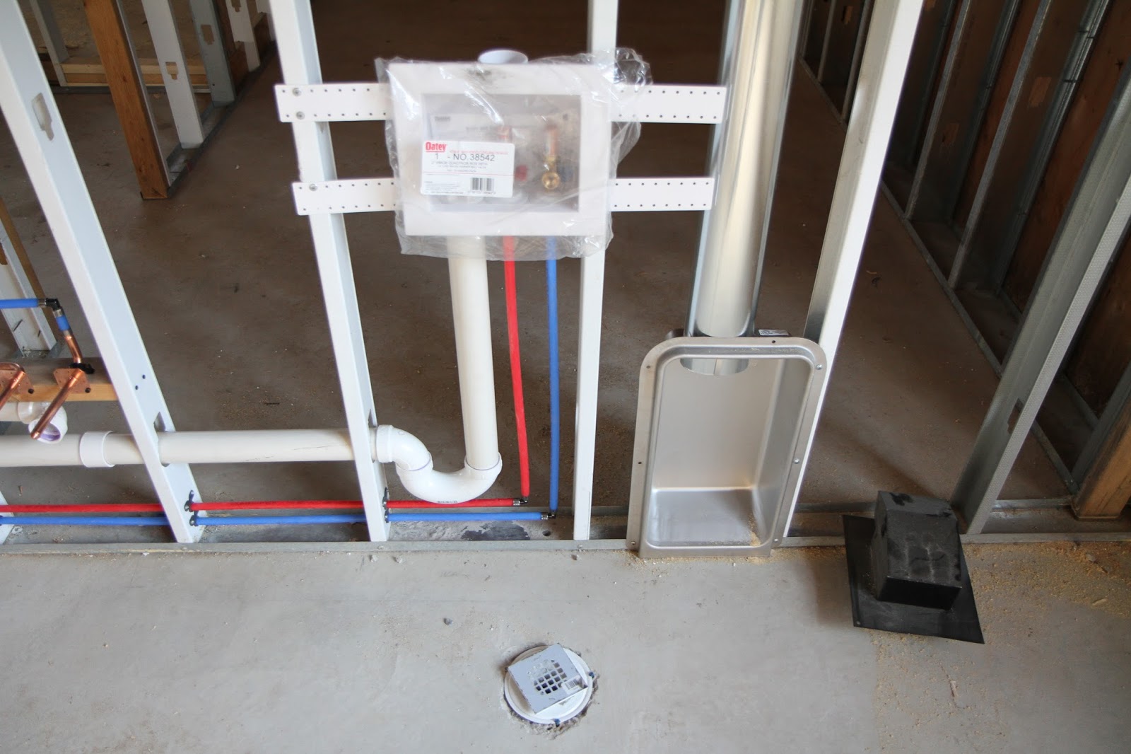
Here's the toilet location in the mudroom bathroom. You can see some of the second floor drain stacks in the walls. It looks like they had some really creative solutions for running some of the pipes. I'm impressed they didn't have to build down any bulkheads yet, and I'm hoping the trend continues. The left vertical pipe is the drain/vent for the sink and the vertical pipe on the right is the drain for the master bathroom and laundry room upstairs.

Here's another look at the two pipes in the wall of the mudroom/storage area, and how it ties into the system. The left pipe is pretty straight forward, the T near the floor will accept the drain for the sink in the bathroom. The pipe continues to extend upward to the attic space to act as the vent for both the sink and the toilet (see wet venting). The pipe on the right goes up through the wall and through the floor above (if I recall correctly) and serves as the main drain for the laundry room, which includes the washing machine and sink basin. The horizontal pipe is in the extra storage space so it's one of the only pipes that drops down below the level of the ceiling so far.

That horizontal pipe is shown here, and isn't tied into anything going down into the basement right now, so I'm not sure where it will connect. We have a drain installed in the floor of the laundry room, right under where the washing machine will be and this is the pipe for that drain. You can see the plumbing for the trap up in the ICF floor that goes over the storage room wall to hook up to the horizontal pipe. Should there be a catastrophic event with the washing machine, this drain will catch all the water before it can become a problem. I highly recommend having something like this in place regardless of which floor your washing machine is on. Could also be used as a drain for mopping the floor, but since it's placed under the machine itself, not perfect for washing down floor soap suds. At least you have the security of a fail safe without having a drain in the middle of the floor.
Also seen pulled through the floor is the first PEX supply tubes run so far. You might be wondering why there are two hot lines and one cold line. These lines supply both the laundry room and master bathroom but that's not why there are two hot lines. There are two hot lines because we're installing a hot water circulation loop. Since all the bathrooms on the second floor are so far away from the water heater in the basement, without this loop, you would have to turn on the hot water tap and wait for the hot water to make its way up through all the plumbing before you get hot water. That's a lot of wasted water that goes down the drain. With this loop, there will be a pump installed inline that can circulate the cold water already present in the pipes, and push it back to the water heater to be heated, rather than going down the drain. The pump will run until it detects the hot water then shut off, so all you have to do is clear the last few feet of cold water from the pipes before you get hot water out of the tap. I'm expecting this type of installation on both the first and second floor. The pump can be run on demand or on a timer and clears the cold trapped water much faster than the flow rate out of a tap so if you manually start the circulation, you would wait less for hot water than if you just had to turn on the tap. At the expense of a little electricity, you're saving water and time.

Another look at that horizontal drain pipe in the storage room. You can see where the laundry room floor drain ties in, and you can see the big drain for the laundry room as well as the vent for the mudroom above the horizontal drain. The storage room itself is passively conditioned, meaning it's inside the envelope of the house but doesn't have a supply or return of its own. This is fine for drains since we don't have to worry about them freezing in cold conditions. Even though the room isn't directly heated, it will never get below freezing.

Here's the supply and drain in the butlers pantry, nothing too exciting yet, but the existence of holes means that they have a plan for the runs and that they didn't have any issues with the concrete beams in this area. It's a positive for the other mechanicals that follow. The HVAC installers were the preliminary scouts for all the pass throughs, but don't have as many as the plumbers. The electricians will be happy to know where they can penetrate because they can see everywhere the plumbers came through. Makes their job a little easier since they have the most penetrations to run.

We found this in the guest room on the first floor. It's a plumbing penetration through the wall to the porch and happens to be a miscommunication that we'll be keeping. I sent blueprints for hose bib locations before the plumbers came through, but my notes on the elevation locations got lost in translation. This was supposed to be on the basement level so we could use it on the side of the house where the landscaping is. It would be to the left of the side basement walk out rather than on the wrap around porch, as it's shown here. There's a correctly placed hose bib on the front of the house and we initially figured we could just run a hose around the side of the house if there's a need for water on the porch. Now that it's in place, we'll just keep it, and request another down below.

Here's the guest room bathroom on the first floor. The drain pipe in the wall is for the second floor shower if I recall correctly. There's a larger drain hole in the wall to the left of this pipe, which I believe will be the toilet/sink drain for the bathroom above. A lot of ICF was removed along the wall for the sink drain and supply, as well as the toilet but no pipes have been installed yet.

Here's what the area under the turret bathroom looks like after the pass throughs are done, but before the plumbing is installed. The 90 degree elbow you see is the drain for the sink. I think the hole in the ICF to the right of it is where the supply water will pass through the floor. The large hole on the left of the frame, hidden up near the nailing wood is for the toilet. This area is a little different because the plumbing fixtures are running perpendicular to the direction of the beams. While all the foam is removable, it's only two inches thick, so I'm not sure how they're planning on running this plumbing without a bulkhead. The closest interior walls are to the left and right with no interior walls in line, parallel to the concrete beams.

On the second floor, this is how they stub out the connections that transition from PEX to copper. I think all the water supplies will end up like this since valves are required to be connected to the plumbing fixtures. The PEX is clamped somehow to these copper stubs and the rest of it can be soldered as traditionally done. This is the hot and cold supply to the turret bathroom, with the drain pass through next to it.
The copper stub is also used for the toilet water supplies, as shown here next to the toilet drain in the turret bathroom. A PVC collar is used to secure the toilet to the floor. Usually they're just connected with wood screws, so I guess they'll have to use cement taping screw to secure the PVC.
Here's the vent stack that comes up from the guestroom bathroom, through the wall and into the attic. This vent will be connected to others and penetrate the roof. They serve two purposes, to vent sewer gases out to the atmosphere and to provide an air source for water draining down the pipe. Without the air source, you would have sinks and tubs trying to suck air to overcome the vacuum created from draining water.

Here's the start of the exciting part of the plumbing and a taste of things to come. This is the drain and water supplies for the master vanity. It's slightly incorrect in that the water supplies are currently placed for a through-counter installtion while we're doing a wall mounted faucet. These are tied into the PEX penetrations shown in a previous picture and are installed along with both sink drains and the vent going up to the attic space. It's really nice they're not directly tied to the drains for the laundry room even though they're close by. Sound from the draining washing machine won't mitigate as badly though the pipes.

Here's where the water to the vanity meets up with with the penetrations through the floor. The two lines coming in on the right are supplies to the master vanity. The higher two supply lines in the 2x6 stud wall is for the laundry room sink basin and the lower two, smaller diameter lines are for the washing machine. You can see the three penetrations through the floor, two red and one blue. If you follow the two red, you can see one just branches off the other, so this is the hot circulation loop. I'm guessing hot water will come up the middle penetration and go back the left one. Every place the PEX passes through the metal studs requires a tubing insulator to prevent damage to the pipe. It's just a plastic collar the PEX pipe can rub against since expansion and contraction, while minimal, does still happen.
The drain stack for the laundry room is to the left of the PEX, the upper one is for the sink basin and the lower is for the washing machine. Again, these have their own vent stack.

Here's the laundry machine location with all the connection boxes in place. You can see the sink basin supplies and drains on the left of the frame. The washing machine supply box is in the middle with the water and drain already connected. Copper stubs are in place ready to accept the valves that will eventually connect to the washing machine. The drain comes out the bottom of the box and the trap is visible and internal to the wall. This wall is shared with the master closet, so I'm not too concerned about noise propagation here. Closets are traditionally quieter because of the sound dampening properties of all the hanging cloth. There's one more port on the top of the box that will be unused. Porter and Heckman installed the dryer vent box, but I'll have to double check the height. We're installing pedestals under each machine so I though this vent box should be installed taller to eliminate u-bends. There will have to be one 90 degree bend coming out the back of the machine, but if it doesn't have to go down, then up again, it would be better. The gas will also be supplied through this box.
You can also see the floor drain which looks properly spaced for finishing tile material. When the tile is installed in this room, they might need to mud with a slope towards the drain.
A little work was performed on the exterior of the house that solved an implementation problem. We were trying to figure out how the cedar shingle will install against the turret windows since they didn't sit very proud of the exterior wall. The elegant solution, shown here, is to install white aluminum flashing over the window nailer and bottom sill so the shingle has a good surface to butt up against. This adds a bit of bulk to the windows, which looks great, and adds a heavier sill to the bottom, also looks great. I'm really happy with this solution.
Here's a close up of the work, which is very professional and clean. All joints are caulked with white sealant and the flashing will extend behind the wood shingle. The flashing is also caulked up against the window frame so these windows are basically double flashed.
Here's a closer look at how the painters taped up the copper before shooting it with primer. We'll have to be sure to get the name of the painters so we can hire them when we need repainting, but I'm hoping this will last at least 10-15 years.
Here's a close up of what the caulked seams in the wood looks like. After it's painted, it really makes the seams in the wood disappear, and it's more apparent on the window trims. Not only does it make a big aesthetic difference, but it also protects the end grain of the wood, which is more prone to water intrusion. Not as important on the overhangs as it is on the window trims.

Another step forward is the installation of the flashing on the wrap around porch. Since the decking ledger board is connected directly to the house and will be interrupting the stone work up to the brick ledge, this flashing was needed so water couldn't penetrate behind the stone. There will be stone above and below the deck so any water that made it's way on the deck and against the house would threaten to run down the house, behind the wood of the deck, and behind the stone. Enough of this would decay the mortar and threaten it's attachment to the stone. This flashing will mitigate that by allowing the water to run off in front of the mortar, over the face of the stone.
Also shown in this picture is the hose bib for the front of the house. Since this is an odd corner, we'll probably have a wall mounted hose reel here that we can use for washing the cars or watering the plants.
Here's what the side of the wrap around porch looks like with all the flashing installed. The flashing is just a thick HDPE and goes behind the stone above it, so there's very little chance of water intrusion. Coupled with the fact that this is under an eight foot porch, I'm pretty confident in this solution.
Even the trim in the gazebo was primed, but there's no reason to prime the porch roof structure. After electrical comes through here, we'll have wood bead board on the ceiling that will need to be primed and painted, but that will probably wait until next spring since it's starting to get too cold to paint.
On to things HVAC. They've started up again installing the main supply and return trunks in the basement and connecting to the first floor as they go along. The second floor is basically finished so it's all about running the first floor trunks and connecting them to the first floor penetrations. One nice surprise is that our final furnace is on site, ready to be installed. It's a
WaterFurnace Series 7 that sports a variable speed compressor and blower. Normal forced air furnaces might have a two speed blower so you can either pump heating or cooling at a gentle quieter speed, or a faster or louder speed. This has an ECM blower capable of 12 speeds so the temperature of the room will always be comfortable and you won't get the ebb and flow temperature a standard single stage furnace provides.

This is the zone controller for the HVAC system. Basically, this is the controller that will control the zones for the house so you can different temperatures in different areas. This one controls up to six zones, but we're going to have it set up for three, one for each floor. This means that there will be a thermostat for each floor so if the upstairs is warmer during the summer, more cool air can be pushed upstairs, which can make its way down to the first floor. We tried to find a use for the other three zones, and may be able to in the future, but as of now, because of the way the house is laid out, really couldn't find a use.

As I mentioned, HVAC work on the main trunks continues to progress. Here's what's going on with the main trunks that will supply and return the front of the house. If you'll recall, we split the front and back of the house to dodge any runs that will need to go under the central beams, allowing for more basement ceiling height. I would have liked these two duct runs to be closer together, and I don't know why they couldn't be right next to each other but now we'll have to find a creative way to box all this stuff in when we finish the basement. They only drop down about a foot, so we still have nine feet under the ducts but it still makes it difficult to manage the ceiling heights. There might be a silver lining here, because now we have a ton of room between the ducts for other mechanicals.

Here they are, looking towards the back yard. The front of the house is on the right and the greatroom is on the left. They're making good use of the cavities in the ICF to run supply runs and the returns look like they connect right up to the main return duct so there are minimal duct lines in the ceiling. This will help with light placement since you can't install recessed lighting where there are duct runs. It looks like they have to go a little farther then they'll terminate the trunks.

The plumbers also removed a section of the slab in the mechanical room in the basement so they could dig under the foundation to bring the water in. Mike was going to see if they could split the sewer and water trench off in the driveway and bring the water in through the front of the house so we didn't have to disturb the slab, but I guess that didn't go through. The water meter is usually inside the house with just a reader that runs to the outside, so I'm not sure why that was rejected. The slab will be re-poured when the installation is done, so I'm not worried about the location. It doesn't look like there's anything down there right now, so I think they were just targeting a depth to get under the footing.

Another point of progress is that we're slowly wading through the beauracracy of getting the water and sewer pulled into the house. The sewer installers confirmed that there is a tap from the sewer line on the other side of my neighbors driveway, and that it runs under the driveway to our property, so that's a good thing. The odd thing is that it's not marked on any city or county records, so it looks like the builder of my neighbors house had it installed, but not inspected. Mike has been battling with the city to get approval on the tap and just succeeded so we have the paperwork to go to the county to get approval on the tap. Once we get the county approval, we can install the lines and be done with it.
In expectation of the approval, the installers have stashed the water and sewer lines, ready to be laid and installed. There's also some larger diameter PVC, which I think is for connecting to the sewer line. Getting these lines installed should have been one of the first things done on the house build, and it will be a big accomplishment.

The black pipes are for the sewer run and they're 2" diameter. Because of the lower elevation of the house in relation to the sewer at the street, we'll need to use a grinder pump, which has two pumps, one redundant, to chew up the "soilds of the house" and push it the 250 feet through the 2" line to the sewer tap. That's a pretty beefy pump. We're not too far down below the sewer level, but 250 feet of 2 inch pipe creates a lot of static head pressure to overcome. The grinder pump is one part of the house that I wished we could do without and it's the one mechanical system I'm most nervous about. Having a redundant pump is nice, but we'll have to be a little more careful with what we put down the drain.

The blue pipe is 1.5" diameter and supplies water to the house. This is a pretty large diameter pipe for the water main supply and I suspect it's that size to mitigate the pressure drop due to the run length. A standard house supply water pipe is 1" and supplies 16 gallons per minute for a fifty foot run. While the extra .5" diameter might not seem like a lot, a 1.5" diameter pipe will supply 25 gallons per minute for a 50' run. Considering we have a 250' run, the size is probably appropriate to maintain pressure and I'm happy it's sized this large.

A large pile of AA stone was also left at the house and I think it's for the water and sewer installation since it's right next to the pipes. I think they lay down the stone around the pipe to demarcate to future diggers that something important is there. The pile is large, but it's not so large to be used as fill for the entire trench and I don't recall DTE using gravel when they laid the electrical lines. I guess we'll just have to wait and see what this is for.

All the utilities are flagged at the street and running up to the house in preparation for digging the water and sewer trenches. These two white stakes were marked by the sewer installer and mark where they need to bore because of the designated wetland culvert that goes under the driveway. It's interesting because the electrical, gas, and telco lines start on the right side of the driveway and bore through here to the left at 36" deep. Now, the sewer and water will start on the left side of the driveway and bore to the right at 48" or deeper (below frost). It will be fun to see how they install the base for the driveway when the time comes. The sides of the driveway is higher on the left and lower on the right, so I think some sand will need to be scraped away to get to the proper depth for the base. Too bad we can't use that sand to fill the near the house.

Here's my neighbors driveway and the path where the sewer line runs. That manhole cover on the other side is for the sewer access and the white paint marks where the end of the tap is on our side. We're lucky someone had the foresight to install this, otherwise we would have had to trench up the driveway a bit and repair it in the spring. The water tap is already on our side of the driveway and should be easy to access.
Every time we go out there, we're reminded why we're putting ourselves through all this difficult process. The road has been really long so far, and there still a long way to go, but at least we're getting some hope for the end. This is just the view off the back part of the wrap around porch. With view like this, it will definitely be worth all the trouble we're going through.